09 Jacdaptor
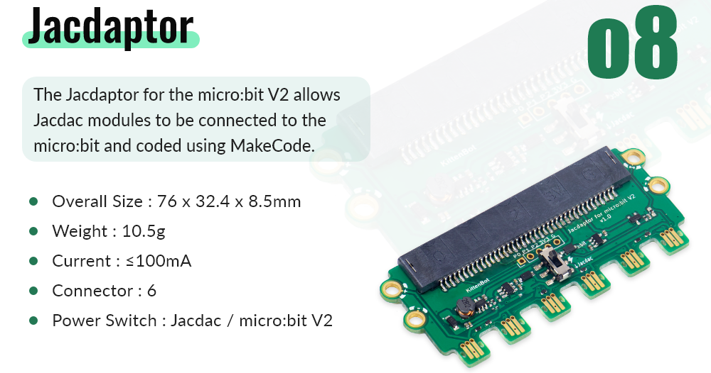
Module Introduction
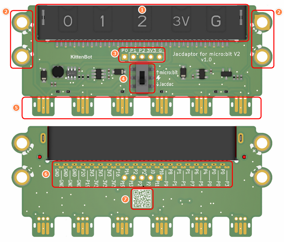
- Microbit Edge Connector
- Jacdac Standard Through Hole
- Micro:bit Gold Finger Pad (P0, P1, P2, 3V3, GND)
- Power Switch
- Jacdac Interface
- Micro:bit Full Interface Out (convenient for Maker welding)
- Product QR Code
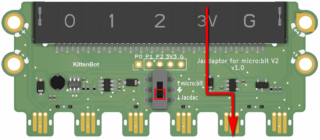
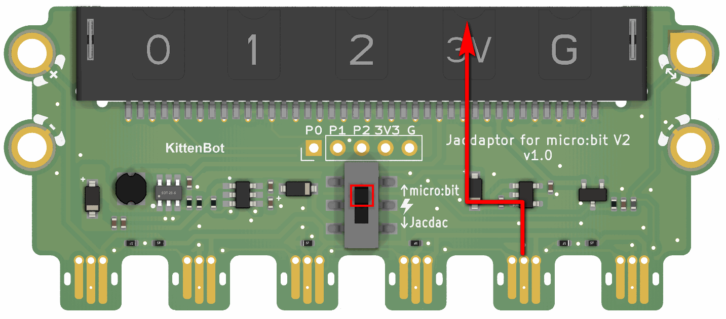
The function of the switch
- When the switch is at the bottom, the power is supplied from Micro:bit to Jacdac interface (commonly used mode, only need to supply power to Microbit with data cable, Jacdac module can work normally)
- When the switch is at the top, the power is supplied from the Jacdac interface to Micro:bit (if you have an external power input, you can use this mode)
FAQ
Q1 :Can Jacdaptor be adapted to MicorbitV1.5?
A1:Jacdaptor can only be used with MicrobitV2
Q2:What is the voltage of Jacdaptor?
A2:5V
Q3:Which mode should the Jacdaptor power switch choose?
A3:It is recommended to switch the switch to the bottom and use Micro:bit to supply power to the Jacdac interface